Difference between revisions of "Select Station"
| (84 intermediate revisions by the same user not shown) | |||
| Line 1: | Line 1: | ||
| − | + | __TOC__ | |
| − | + | <BR /> | |
| − | = | + | =Primary Station= |
| − | + | This tab allows to specify the stations you have connected to your Meteobridge. Standard setups will just have one station defined as "Primary" station. | |
| − | + | ||
| − | + | ||
| − | + | ||
| − | ==Station Altitude== | + | ==Station Selection== |
| − | It is | + | Meteobridge does not provide an automatic recognition of the station being connected, but when you click on the "Model" drop-down box you get an crossed box symbol in front the model name when Meteobridge thinks the station is currently not connected, a check-marked box symbol when Meteobridge thinks the station is connected, and an empty box symbol when it does not know. |
| + | The list of supported stations is rather long and also depends on the Meteobridge Model you are using. When you are with a NANO (as in the example) then you don't get stations offered to be connected via USB, because the NANO does not provide a USB port. In that case you are limited to the Davis console or Envoy the NANO is plugged into and stations you can connect to via TCP/IP. | ||
| + | |||
| + | [[File:page1.png]] | ||
| + | |||
| + | Meteobridge PRO and NANO offer a "use internal console connection" or "use internal RF receiver" checkbox. This checkbox should be enabled unless you don't want to make use of these signature features of the NANO or PRO. | ||
| + | |||
| + | ====<font color="red">Limitation on USB 1.x Stations</font>==== | ||
| + | Please be aware that Meteobridge client hardware from TP-Link (TL-MR3020 and TL-WR703N) and D-Link (DIR-505) is not able to run old USB 1.x devices directly, but needs a small cheap, unpowered external USB 2.0 hub in between, which translates USB 1.x from your weather station to USB 2.0. Please check list of supported stations [http://www.meteobridge.com/wiki/index.php/Stations here], to learn in which situation you ned a USB 2.0 hub inbetween. As USB 2.0 hubs are available all around and do just cost a few dollars, this should be a no brainer. Meteobridge PRO users do not need a USB hub, no issues there. | ||
| + | |||
| + | ==Station selection== | ||
| + | Meteobridge supports the most popular weather stations in the market. Stations with a serial RS232 interface can be connected by a cheap RS232-USB converter. Converters with PL230x, CP210x and FTDI chipsets are supported by Meteobridge. Some of the weather stations have specifics you should know when using these with Meteobridge. | ||
| + | |||
| + | ===Davis Vantage Pro and Vue=== | ||
| + | These stations can be equipped with an IP-based Logger called WLIP. If you have one of these, please select WLIP operation (and how often Meteobridge should pause to allow upload to Davis Weatherlink services in parallel to Meteobridge operation) and enter IP and port (separated by a colon) in the input field next to the selection box (example: "192.168.1.222:10001"). This will tell Meteobridge to connect this station not via USB but via your LAN/WLAN (in the example on IP 192.168.1.222 at port 10001). When you don't specify a port, the WLIP default port (22222) is used. | ||
| + | |||
| + | [[File:davissetup1.png]] | ||
| + | |||
| + | When you have a serial data logger you can map that to USB by a FTDI or PL2303 based serial to USB converter. When Vantage is connected via USB to Meteobridge please make sure that baud rate of Vantage is set to 19200, otherwise no connection can be established. Since Version 2.5 Meteobridge allows parallel use of the Vantage by a PC program, which connects to the Meteobridge on port 22222 (like with a Davis IP logger). | ||
| + | |||
| + | [[File:davissetup2.png]] | ||
| + | |||
| + | When you select these stations an additional input area will appear, where you can configure basic settings of your Davis weather station. Apart from the date/time synchronization these configuration settings are just applied once. Doing these initial setup within Meteobridge spares you to fiddle manually with the console or with the Davis PC program. Picture below shows which settings can be made. If you need more detail to understand what these settings do, please consult you Davis manual. In the example below the main Vantage ISS sensor is received on transmitter ID #3, while the additional temperature/humidity sensor is received via a repeater sending on channel A and on transmitter ID #1. This sensor is mapped to the additional temperature with ID #1 in the data protocol of the console. Additionally, the received data will be retransmitted by the console on transmitter ID #2. | ||
| + | |||
| + | ===Davis WeatherLink Live=== | ||
| + | When you connect to a Davis WLL you need to specify which sensors you expect being connected. The attached example specifies an ISS connected at transmitter ID #3 and with a rain bucket size of 0.2mm. You can add more sensors by the "add transmitter" drop-down box. | ||
| + | |||
| + | [[File:wllsetup.png]] | ||
| + | |||
| + | ===Meteostick and Red Cap Meteobridge PRO=== | ||
| + | Meteostick needs selection of a RF band to work with. Please select the setting that matches your geography. In addition you also have to define an RF sensitivity. Please make sure that that is about 10db more sensitive than signal level from incoming data. When you see data coming in on "Live Data" tab with -70db for example, then -80db is a good sensitivity level. Increasing sensitivity of the receiver too much will collect tons of RF noise which will disturb picking up valid data significantly. For normal Davis operation "direct" bandwidth setting is best. If you want to work with signals retransmitted from your Vantage console, please switch to "via console" to limit dropped packets. | ||
| + | |||
| + | [[File:page1-mbpro.png]] | ||
| + | |||
| + | The "Add Station" button allows you to select a station number (which is the transmitter ID your station is using). Having done that, an empty station field will be added to the list of stations and you are asked to specify what kind of station you like to add. Available station types are ISS, Wind, Rain, Temperature, Temperature/Humidity and Leaf/Soil. When you made the selection, please press "save" to make selection permanent. When a station should be removed, select station type "none" and press "save". Example below shows a configuration of a Wind station on transmitter ID #1, an ISS on ID #3, a Temperature station on ID #4 and a Leaf/Soil station on ID #7. | ||
| + | |||
| + | Meteobridge uses the schema explained below to give sensors a consistent naming: | ||
| + | * First ISS is taken (here ID #3) and its sensors are mapped to "th0", "wind0", "rain0", "uv0", "sol0" | ||
| + | * If a dedicated Wind station is found (here ID #1) the wind sensor from this station is assumed to be the primary one, so it is mapped to "wind0". Wind sensor of ISS which has been formaly mapped to "wind0" is remapped to its station number, here "wind4". | ||
| + | * A dedicated Rain station is handled like a Wind station and sensor name "rain0" is applied to it. | ||
| + | * The first Leaf/Soil station in the list is mapped to sensors "th10", "th11", ... , "th18". Follow-on Leaf/Soil stations are mapped to name ranges "th20, ..." for station ID #1, "th30, ..." for station ID #2, and so on. | ||
| + | * Temperature and Temperature/Humidity stations are are mapped to "thX" resp. "tX", where X is the station ID. | ||
| + | * Additional Wind/Rain/ISS stations have their sensors indexed with the station ID, like Temperature and Temperature/Humidity sensor mentioned before. | ||
| + | |||
| + | ===Acurite Internet-Bridge=== <!--T:13--> | ||
| + | This can only be used when Meteobridge is connected to your LAN via WiFi as it needs the LAN port to be directly connected to the Acurite Internet-Bridge by means of an Ethernet cable. Furthermore, "LAN Bridge" option on network tab must be enabled, to allow the Acurite Internet-Bridge to connect to the Internet as before. Having done that Meteobridge will sniff weather data from the TCP traffic the Acurite Internet-Bridge will pass through Meteobridge. Sniffed data appears in Meteobridge the same way as from the other weather stations. | ||
| + | |||
| + | ===Ambientweather/Fine Offset=== <!--T:17--> | ||
| + | These stations are availbale with or without UV/solar sensor. The drop down behind this type of stations allows to control if Meteobridge should try reading UV/solar data from it. | ||
| + | |||
| + | ==Using Multiple Stations== | ||
| + | Since version 4.4 Meteobridge allows to have more than one weather station connected and evaluated at a time. In order to add another station you simply press the "add weather station" button and a new tab named "station #1" will appear. Configuration of this additional weather station is done exactly like on the "primary station" tab. Available station models might be a bit reduced as Meteobridge cannot distinguish multiple instances of some USB HID stations and therefor restricts to use just one of those. | ||
| + | When you use multiple station connected via USB serial you have to choose the most distintive identifier in the "Device" select box. An entry like "/dev/ttyMH113" specifies a certain physical USB port of your Meteobridge. When you use this, Meteobridge cannot mess up between all the connected USB serial devices. When you just have one USB serial device connected, "/dev/ttyMH" will be fine as the physical USB port the station is connected to does not matters as there is just one station and when you connect your station to another physical USB port it will still work. | ||
| + | "no restart of logger when lacking data from this station" should be used when using multiple stations and you want to avoid to cycle to a reset of all connected stations when one station does not provide data anymore. Sometime a complete shutdown of the USB drivers can help to resurrect a stalled USB connection, but to have also the stations doing fine impacted by that might be something you want to avoid. | ||
| + | Additional weather station tabs also offer a "remove weather station" button which can be used for removing this tab and settings again. | ||
| + | |||
| + | =Weather Cam= | ||
| + | Since version 1.6 Meteobridge supports use of a Ubiquiti AirCam as a weather cam. All you need to do is to connect the AirCam to your LAN (or to Meteobrige's LAN port when configured in bridging mode as explained on [[Setup Network]] page), set AirCam selection mark, insert AirCam's IP and password ("ubnt" is factory default) and press "Save". If a red cross appears left to the selected mark, press "Initialize Cam" to configure cam in a way needed for Meteobridge. After that a green mark should appear. If not, please inspect error messages on top of page. Initialization of cam only needs to be done once. Meteobridge does only support Ubiquiti AirCam right now, other cams won't do. | ||
| + | |||
| + | If you don't have an Ubiquiti AirCam connected but you have an URL pointing to an image that Meteobridge should take as weather camera image, you can use the "External Picture" option. Meteobridge reads the URL and uses the image for further processing and upload to weather networks. To use the image of an external camera might be interesting if you want to have your Meteobridge weather data added to that image. How to add weather data to an image is explained on [[Stations]] page. | ||
| + | |||
| + | =Settings= | ||
| + | There are a couple of adjustments to your station setup to optimize quality of your sensor readings. | ||
| + | |||
| + | [[File:statsettings.png]] | ||
| + | |||
| + | ==Calibration== | ||
| + | All Meteobridge sensors can be calibrated. this is done by an offset and a factor which allows for any linear sensor calibration. Please keep in mind that pressur and sealevel pressure are separate sensors in Meteobridge, therefore, you have to apply the calibration to both, same with temperature and dew point. Example above adds 2.5 hPa to the pressure sensors and half a degree Celsius to the primary outdoor temp-hum sensor. | ||
| + | Calibration can be done by selecting a sensor from the "add sensor" drop-down box and specifying the offset and factor values. Having done this pressing "save" is needed to make the changes permanent and operational. Sensor calibration is effective on the raw data and is effective from the moment you define it, but it does not affect already logged sensor data. | ||
| + | |||
| + | ==Station Altitude== | ||
| + | It is important that you specify the station altitude. Meteobridge uses altitude information to compute sealevel pressure used by weather networks. You can specify altitude in meters or feet, please set down-down box for selection of "meters" or "feet" accordingly. | ||
==Tolerated Data Age== | ==Tolerated Data Age== | ||
| − | Meteobridge needs to know how long a sensor value should be regarded valid. Standard is 10 minutes, it is not | + | Meteobridge needs to know how long a sensor value should be regarded valid. Standard is 10 minutes, it is not recommended to go below that value. If your weather station does have RF problems with certain sensors that only change slowly over time it might be a good move, to increase the value. When you don't know, stay with the default of 10 minutes. |
| − | == | + | ==Historical Data Save Interval== |
| − | + | Meteobridge stores cumulated historical data every 10 minutes to Meteobridge server to have this data saved in case of a power failure or unexpected shut down. Default interval of "every 10 minutes" can be changed to less often intervals up to once a day. This might be useful to spare bandwidth, when your Meteobridge operates on a very remote location. When you are using a Meteobridge PRO or NANO SD this feature of uploading data to a server in the Internet is not used for making data persistent, but local storage is used instead. | |
| − | [[File: | + | =Mapping= |
| + | With the introduction of multiple stations Meteobridge has to find a way to tell which sensors of which station should be used for what purpose in regard to weather network uploads and other operations. This is done by mapping the "physical" sensors of a particular station to the "logical" sensors used for uploading data. The "mapping" tab is predefined with obvious mappings when having just one primary station connected, but you can chnage this by selecting a physical sensor with "select sensor" dropdawn. having seleted a physical sensor you are asked to give it a meaning by mapping it to a logical sensor. | ||
| + | |||
| + | [[File:mapsensor.png]] | ||
| + | |||
| + | Example above shows default mappings in green and individual mapping in yellow. The individual mapping says that "primary outdoor temp/hum sensor" from additional station #1 should be taken as the "primary outdoor temp/hum sensor" when reporting to weather networks. To realize this the temp/hum/dew sensors "th1!0xxx" are mapped to "th0xxx". Physical sensor names are composed of | ||
| + | * the sensor category (t, th, thb, wind, rain, uv, sol, air, ...) | ||
| + | * station number (0 = primary station) | ||
| + | * exclamation mark "!" as delimiter | ||
| + | * sensor number (0 = primary sensor of the specific station) | ||
| + | * sensor type (temp, hum, dew, ...) | ||
| + | Therefore, "th1!0temp" is the primary temp outdoor sensor of station #1. | ||
| + | |||
| + | With "reset" button all individual sensor mappings are removed and defaults are applied again. | ||
| + | When you press "Save" weather station selection is made permanent and data logger is restarted to adapt to the new settings. | ||
Latest revision as of 14:59, 25 October 2020
Primary Station
This tab allows to specify the stations you have connected to your Meteobridge. Standard setups will just have one station defined as "Primary" station.
Station Selection
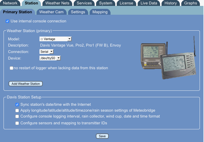
Meteobridge does not provide an automatic recognition of the station being connected, but when you click on the "Model" drop-down box you get an crossed box symbol in front the model name when Meteobridge thinks the station is currently not connected, a check-marked box symbol when Meteobridge thinks the station is connected, and an empty box symbol when it does not know. The list of supported stations is rather long and also depends on the Meteobridge Model you are using. When you are with a NANO (as in the example) then you don't get stations offered to be connected via USB, because the NANO does not provide a USB port. In that case you are limited to the Davis console or Envoy the NANO is plugged into and stations you can connect to via TCP/IP.
Meteobridge PRO and NANO offer a "use internal console connection" or "use internal RF receiver" checkbox. This checkbox should be enabled unless you don't want to make use of these signature features of the NANO or PRO.
Limitation on USB 1.x Stations
Please be aware that Meteobridge client hardware from TP-Link (TL-MR3020 and TL-WR703N) and D-Link (DIR-505) is not able to run old USB 1.x devices directly, but needs a small cheap, unpowered external USB 2.0 hub in between, which translates USB 1.x from your weather station to USB 2.0. Please check list of supported stations here, to learn in which situation you ned a USB 2.0 hub inbetween. As USB 2.0 hubs are available all around and do just cost a few dollars, this should be a no brainer. Meteobridge PRO users do not need a USB hub, no issues there.
Station selection
Meteobridge supports the most popular weather stations in the market. Stations with a serial RS232 interface can be connected by a cheap RS232-USB converter. Converters with PL230x, CP210x and FTDI chipsets are supported by Meteobridge. Some of the weather stations have specifics you should know when using these with Meteobridge.
Davis Vantage Pro and Vue
These stations can be equipped with an IP-based Logger called WLIP. If you have one of these, please select WLIP operation (and how often Meteobridge should pause to allow upload to Davis Weatherlink services in parallel to Meteobridge operation) and enter IP and port (separated by a colon) in the input field next to the selection box (example: "192.168.1.222:10001"). This will tell Meteobridge to connect this station not via USB but via your LAN/WLAN (in the example on IP 192.168.1.222 at port 10001). When you don't specify a port, the WLIP default port (22222) is used.
When you have a serial data logger you can map that to USB by a FTDI or PL2303 based serial to USB converter. When Vantage is connected via USB to Meteobridge please make sure that baud rate of Vantage is set to 19200, otherwise no connection can be established. Since Version 2.5 Meteobridge allows parallel use of the Vantage by a PC program, which connects to the Meteobridge on port 22222 (like with a Davis IP logger).
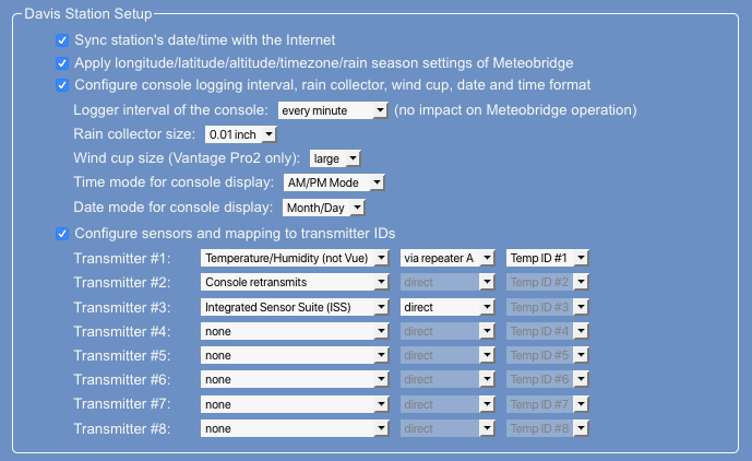
When you select these stations an additional input area will appear, where you can configure basic settings of your Davis weather station. Apart from the date/time synchronization these configuration settings are just applied once. Doing these initial setup within Meteobridge spares you to fiddle manually with the console or with the Davis PC program. Picture below shows which settings can be made. If you need more detail to understand what these settings do, please consult you Davis manual. In the example below the main Vantage ISS sensor is received on transmitter ID #3, while the additional temperature/humidity sensor is received via a repeater sending on channel A and on transmitter ID #1. This sensor is mapped to the additional temperature with ID #1 in the data protocol of the console. Additionally, the received data will be retransmitted by the console on transmitter ID #2.
Davis WeatherLink Live
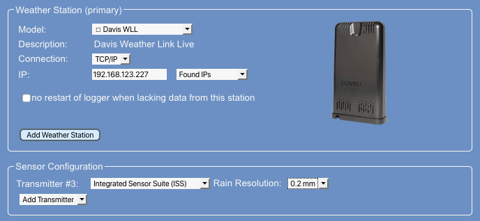
When you connect to a Davis WLL you need to specify which sensors you expect being connected. The attached example specifies an ISS connected at transmitter ID #3 and with a rain bucket size of 0.2mm. You can add more sensors by the "add transmitter" drop-down box.
Meteostick and Red Cap Meteobridge PRO
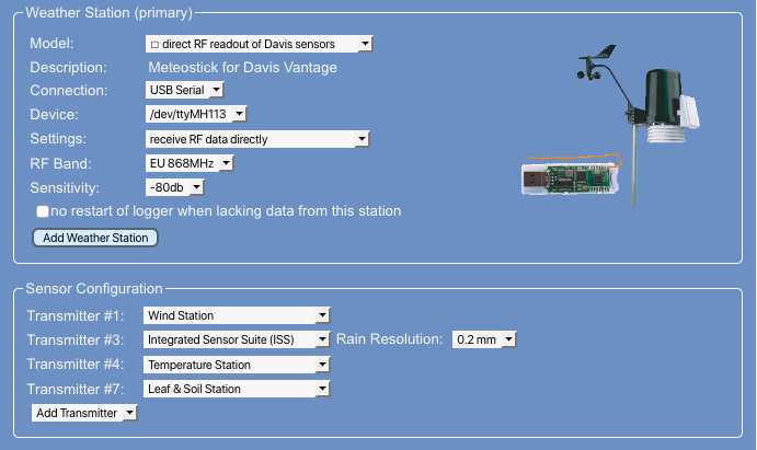
Meteostick needs selection of a RF band to work with. Please select the setting that matches your geography. In addition you also have to define an RF sensitivity. Please make sure that that is about 10db more sensitive than signal level from incoming data. When you see data coming in on "Live Data" tab with -70db for example, then -80db is a good sensitivity level. Increasing sensitivity of the receiver too much will collect tons of RF noise which will disturb picking up valid data significantly. For normal Davis operation "direct" bandwidth setting is best. If you want to work with signals retransmitted from your Vantage console, please switch to "via console" to limit dropped packets.
The "Add Station" button allows you to select a station number (which is the transmitter ID your station is using). Having done that, an empty station field will be added to the list of stations and you are asked to specify what kind of station you like to add. Available station types are ISS, Wind, Rain, Temperature, Temperature/Humidity and Leaf/Soil. When you made the selection, please press "save" to make selection permanent. When a station should be removed, select station type "none" and press "save". Example below shows a configuration of a Wind station on transmitter ID #1, an ISS on ID #3, a Temperature station on ID #4 and a Leaf/Soil station on ID #7.
Meteobridge uses the schema explained below to give sensors a consistent naming:
- First ISS is taken (here ID #3) and its sensors are mapped to "th0", "wind0", "rain0", "uv0", "sol0"
- If a dedicated Wind station is found (here ID #1) the wind sensor from this station is assumed to be the primary one, so it is mapped to "wind0". Wind sensor of ISS which has been formaly mapped to "wind0" is remapped to its station number, here "wind4".
- A dedicated Rain station is handled like a Wind station and sensor name "rain0" is applied to it.
- The first Leaf/Soil station in the list is mapped to sensors "th10", "th11", ... , "th18". Follow-on Leaf/Soil stations are mapped to name ranges "th20, ..." for station ID #1, "th30, ..." for station ID #2, and so on.
- Temperature and Temperature/Humidity stations are are mapped to "thX" resp. "tX", where X is the station ID.
- Additional Wind/Rain/ISS stations have their sensors indexed with the station ID, like Temperature and Temperature/Humidity sensor mentioned before.
Acurite Internet-Bridge
This can only be used when Meteobridge is connected to your LAN via WiFi as it needs the LAN port to be directly connected to the Acurite Internet-Bridge by means of an Ethernet cable. Furthermore, "LAN Bridge" option on network tab must be enabled, to allow the Acurite Internet-Bridge to connect to the Internet as before. Having done that Meteobridge will sniff weather data from the TCP traffic the Acurite Internet-Bridge will pass through Meteobridge. Sniffed data appears in Meteobridge the same way as from the other weather stations.
Ambientweather/Fine Offset
These stations are availbale with or without UV/solar sensor. The drop down behind this type of stations allows to control if Meteobridge should try reading UV/solar data from it.
Using Multiple Stations
Since version 4.4 Meteobridge allows to have more than one weather station connected and evaluated at a time. In order to add another station you simply press the "add weather station" button and a new tab named "station #1" will appear. Configuration of this additional weather station is done exactly like on the "primary station" tab. Available station models might be a bit reduced as Meteobridge cannot distinguish multiple instances of some USB HID stations and therefor restricts to use just one of those. When you use multiple station connected via USB serial you have to choose the most distintive identifier in the "Device" select box. An entry like "/dev/ttyMH113" specifies a certain physical USB port of your Meteobridge. When you use this, Meteobridge cannot mess up between all the connected USB serial devices. When you just have one USB serial device connected, "/dev/ttyMH" will be fine as the physical USB port the station is connected to does not matters as there is just one station and when you connect your station to another physical USB port it will still work. "no restart of logger when lacking data from this station" should be used when using multiple stations and you want to avoid to cycle to a reset of all connected stations when one station does not provide data anymore. Sometime a complete shutdown of the USB drivers can help to resurrect a stalled USB connection, but to have also the stations doing fine impacted by that might be something you want to avoid. Additional weather station tabs also offer a "remove weather station" button which can be used for removing this tab and settings again.
Weather Cam
Since version 1.6 Meteobridge supports use of a Ubiquiti AirCam as a weather cam. All you need to do is to connect the AirCam to your LAN (or to Meteobrige's LAN port when configured in bridging mode as explained on Setup Network page), set AirCam selection mark, insert AirCam's IP and password ("ubnt" is factory default) and press "Save". If a red cross appears left to the selected mark, press "Initialize Cam" to configure cam in a way needed for Meteobridge. After that a green mark should appear. If not, please inspect error messages on top of page. Initialization of cam only needs to be done once. Meteobridge does only support Ubiquiti AirCam right now, other cams won't do.
If you don't have an Ubiquiti AirCam connected but you have an URL pointing to an image that Meteobridge should take as weather camera image, you can use the "External Picture" option. Meteobridge reads the URL and uses the image for further processing and upload to weather networks. To use the image of an external camera might be interesting if you want to have your Meteobridge weather data added to that image. How to add weather data to an image is explained on Stations page.
Settings
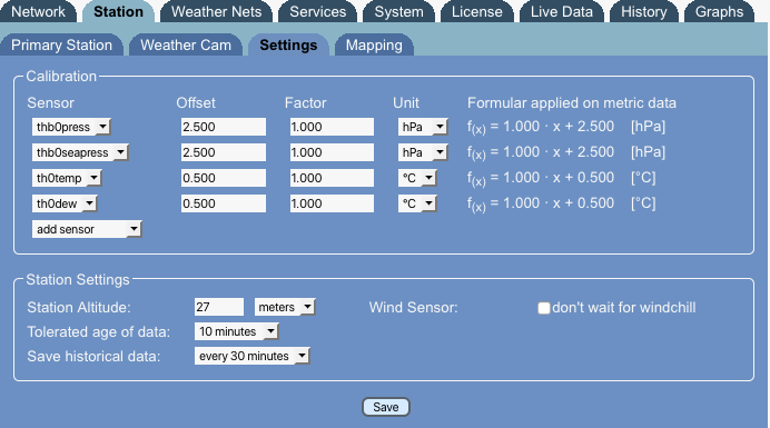
There are a couple of adjustments to your station setup to optimize quality of your sensor readings.
Calibration
All Meteobridge sensors can be calibrated. this is done by an offset and a factor which allows for any linear sensor calibration. Please keep in mind that pressur and sealevel pressure are separate sensors in Meteobridge, therefore, you have to apply the calibration to both, same with temperature and dew point. Example above adds 2.5 hPa to the pressure sensors and half a degree Celsius to the primary outdoor temp-hum sensor. Calibration can be done by selecting a sensor from the "add sensor" drop-down box and specifying the offset and factor values. Having done this pressing "save" is needed to make the changes permanent and operational. Sensor calibration is effective on the raw data and is effective from the moment you define it, but it does not affect already logged sensor data.
Station Altitude
It is important that you specify the station altitude. Meteobridge uses altitude information to compute sealevel pressure used by weather networks. You can specify altitude in meters or feet, please set down-down box for selection of "meters" or "feet" accordingly.
Tolerated Data Age
Meteobridge needs to know how long a sensor value should be regarded valid. Standard is 10 minutes, it is not recommended to go below that value. If your weather station does have RF problems with certain sensors that only change slowly over time it might be a good move, to increase the value. When you don't know, stay with the default of 10 minutes.
Historical Data Save Interval
Meteobridge stores cumulated historical data every 10 minutes to Meteobridge server to have this data saved in case of a power failure or unexpected shut down. Default interval of "every 10 minutes" can be changed to less often intervals up to once a day. This might be useful to spare bandwidth, when your Meteobridge operates on a very remote location. When you are using a Meteobridge PRO or NANO SD this feature of uploading data to a server in the Internet is not used for making data persistent, but local storage is used instead.
Mapping
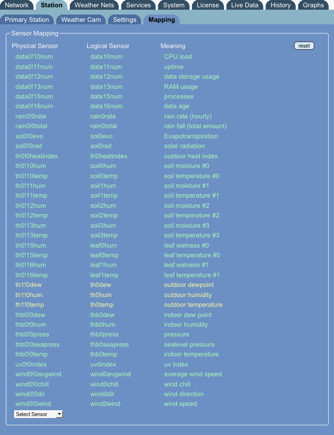
With the introduction of multiple stations Meteobridge has to find a way to tell which sensors of which station should be used for what purpose in regard to weather network uploads and other operations. This is done by mapping the "physical" sensors of a particular station to the "logical" sensors used for uploading data. The "mapping" tab is predefined with obvious mappings when having just one primary station connected, but you can chnage this by selecting a physical sensor with "select sensor" dropdawn. having seleted a physical sensor you are asked to give it a meaning by mapping it to a logical sensor.
Example above shows default mappings in green and individual mapping in yellow. The individual mapping says that "primary outdoor temp/hum sensor" from additional station #1 should be taken as the "primary outdoor temp/hum sensor" when reporting to weather networks. To realize this the temp/hum/dew sensors "th1!0xxx" are mapped to "th0xxx". Physical sensor names are composed of
- the sensor category (t, th, thb, wind, rain, uv, sol, air, ...)
- station number (0 = primary station)
- exclamation mark "!" as delimiter
- sensor number (0 = primary sensor of the specific station)
- sensor type (temp, hum, dew, ...)
Therefore, "th1!0temp" is the primary temp outdoor sensor of station #1.
With "reset" button all individual sensor mappings are removed and defaults are applied again. When you press "Save" weather station selection is made permanent and data logger is restarted to adapt to the new settings.
